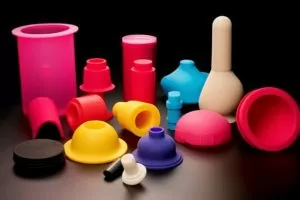
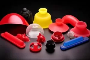
The structure of thermoset liquid silicone rubber (LSR) injection molds is generally similar to that of molds used for thermoplastic compounds, but there are several significant differences.
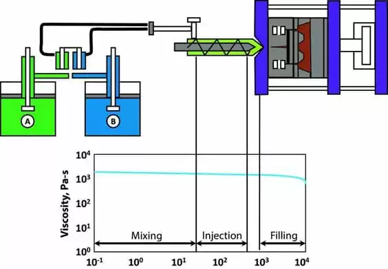
For example, LSR compounds generally have a low viscosity and therefore very short filling times, even at very low injection pressures. To avoid air trapping, it is essential to have a good air venting device in the mold.
In addition, LSR compounds do not shrink as much as thermoplastic compounds in the mold; they tend to expand when hot and shrink slightly when cold. As a result, the product does not always remain on the convex side of the mold as expected but is retained in the cavity with a larger surface area.
1. Shrinkage
Although LSR do not shrink in the mold, they often shrink 2.5% to 3% after demolding and cooling. The exact amount of shrinkage depends to some extent on the formulation of that compound.
However, from a mold perspective, shrinkage can be influenced by several factors, including the temperature of the mold, the temperature of the compound when it is demolded, as well as the pressure in the mold cavity, and the subsequent compression of the compound.
The location of the injection point is also worth considering, as the shrinkage in the direction of the adhesive flow is usually greater than the shrinkage in the direction perpendicular to the adhesive flow.
The size of the product also affects its shrinkage, with thicker products generally having less shrinkage than thinner ones. If secondary vulcanization is required, the shrinkage may be an additional 0.5%-0.7%.
2. Parting line
Determining the location of the parting line is one of the first few steps in designing a silicone rubber injection mold. Venting is achieved mainly using grooves located on the parting line, which must be in the area where the injection compound will last. This helps to avoid internal air bubbles and to reduce the loss of strength at the glue joint.
Due to the low viscosity of LSR, the parting line must be precise to avoid spillage. Even so, parting lines can often be seen on shaped products. Mold release is influenced by the geometry of the part and the position of the parting surface. Designing the part with a slight chamfer will help ensure a consistent affinity for the desired other half of the injection mold cavity.
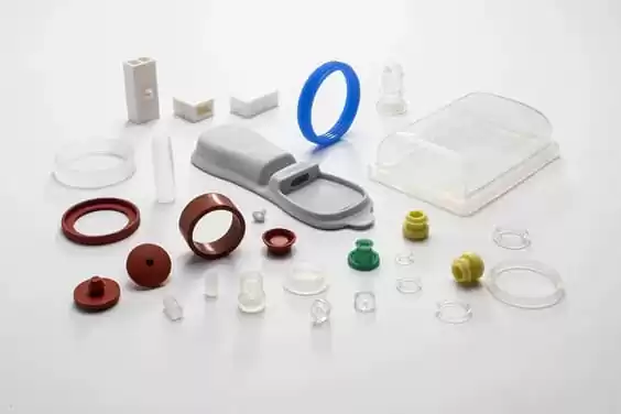
3. Venting
As the LSR is injected, the air trapped in the cavity is compressed as the mold closes and then expelled through the venting grooves as the mold fills.
If the air is not completely exhausted, it will be trapped in the adhesive (which often results in a part of the product showing white edges). The venting grooves are generally mm-3mm wide and 0.004mm-0.005mm deep.
The best venting effect can be created by vacuuming inside the mold. This is achieved by designing a gasket on the parting line and quickly evacuating all cavities to vacuum with a vacuum pump. Once the vacuum has reached the rated level, the mold is fully closed and the injection press begins.
Some injection molding equipment allows operation at variable closing forces, which allows the processor to close the mold at low pressure until 90-95% of the cavity is filled with LSR (making it easier for air to escape), and then switch to a higher closing force to avoid silicone rubber expansion and overflow.
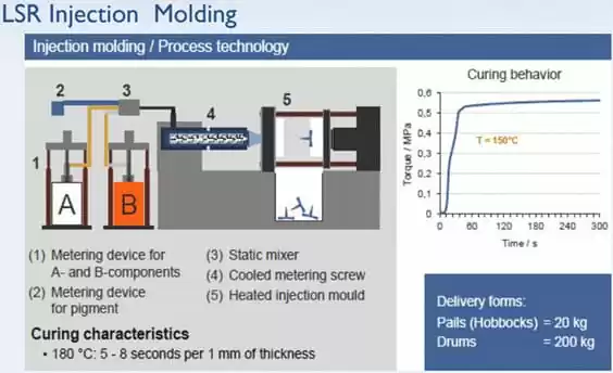
4. Injection point
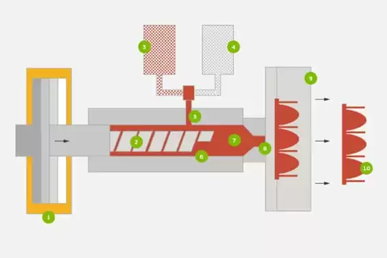
A cold runner system is used when molding LSR. The advantages of this silicone rubber can be maximized and the production efficiency can be increased to the maximum.
By processing products in such a way, it is not necessary to remove the injection channel, thus avoiding increased labor for the operation and sometimes a large amount of material waste. In many cases, lane-free construction also reduces operating time.
The injection nozzle is controlled by a needle valve for positive flow, and many manufacturers now offer nozzles with pneumatic switches as standard equipment and can be set up in various parts of the mold.
Some injection mold makers have developed an open cold runner system that is so small that multiple injection points (and thus the entire cavity) have to be set in a very limited mold space.
This technology makes it possible to produce large quantities of high-quality silicone rubber products without having to separate the injection ports.
If a cold runner system is used, it is important to create an effective temperature separation between the hot cavity and the cold runner. If the runner is too hot, the rubber may start to vulcanize before it is injected. But if it cools too rapidly, it will absorb too much heat from the sprue area of the injection mold, resulting in incomplete vulcanization.
For products injected with conventional sprue (e.g. submerged sprue and conical sprue), it is appropriate to use a small diameter injection port (usually 0.2mm-0.5mm) for injection.
With low viscosity LSR compounds, as with thermoplastic compounds, it is important to balance the runner system so that all cavities are evenly filled with the compound. Simulation software for designing the runner system can greatly simplify the development of the mold and prove its effectiveness using mold filling tests.
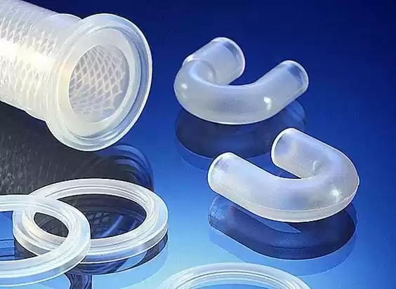
5. Demolding
Liquid silicone molding, through vulcanization, tends to adhere to the surface of the metal, and the flexibility of the product can make it difficult to release. The high-temperature tear strength of LSR allows it to be released under normal conditions without damage to even larger products.
The most common release techniques include stripper plate release, stripper pin release, and pneumatic release. Other common techniques are roller scraping, export plate release, and automatic mold release.
When using a release system, it is important to keep it within a high degree of accuracy. If there is too much clearance between the top push pin and the guide pin sleeve, or if the gap between the parts becomes large due to wear over time, glue spillage may result.
The inverted conical or mushroom-shaped top push pin is very effective because it allows a larger contact pressure to be applied and facilitates the improvement of the sealing purpose.
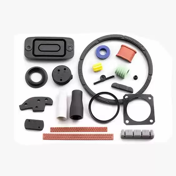
6. Mould material
Mold pallets are often made of non-alloy tool steel (no.1.1730, DIN code C45W). For mold pallets that need to withstand the high temperature of 170℃-210℃, they should be made of pre-tempered steel (no.1.2312, DIN code 40 CrMn-M oS 8 6) in consideration of impact resistance.
For mold pallets with mold cavities, they should be made of nitrided or tempered heat-treated ethyl tool steel to ensure their high-temperature resistance.
For LSRs with high filling capacity, such as oil-resistant grade LSRs, it is recommended to use harder materials for the manufacture of the molds, such as bright chrome plated steel or powdered metal specially developed for this purpose (no.1.2379, DINcode X 155 CrVMo121).
When designing injection molds for high-wear materials, those parts that are subject to high friction should be designed to be formed in a replaceable manner so that the entire mold does not have to be replaced.
The inner surface of the mold cavity has a significant impact on the finish of the product. The most obvious is that the shaped product will match the surface of the cavity perfectly. Injection molds for transparent products should be made of polished steel. Surface-treated Chin/Nickel steel is extremely wear-resistant, while PTFE/Nickel makes mold release easier.
7. Temperature control
Generally speaking, the molding of LSR is preferable to be heated by electric heating, usually by band heaters, cartridge heaters, or heating plates.
The key is to make the temperature field evenly distributed throughout the mold to promote uniform curing of LSR. On large molds, is a cost-effective heating method when pushing oil temperature control heating.
Wrapping the mold with an insulating plate helps to reduce heat loss. The unsuitability of any part of the hot mold may cause it to suffer from large temperature fluctuations between operating processes or cause air runs.
If the surface temperature drops too low, the curing speed of the adhesive will be slowed down, which often prevents the product from being released from the injection mold and causes quality problems.
A certain distance should be maintained between the heater and the parting line to prevent the template from bending and deforming and forming an overflow glue burr on the finished product. If the mold is designed with a cold runner system, the hot end and cold end must be completely separated from each other.
Special Chin alloys (e.g. 3.7165 [TiA16V4]) can be used, because of their much lower thermal conductivity compared to other steels. For an integral injection mold heating system, the heat shield should be set between the mold and the mold pallet to minimize heat loss. Proper design and conception can ensure LSR injection molding, where the mold is very important.
The above mold design principles are aimed at filling the mold cavity with rubber, shortening the curing time, and achieving superior quality and high yield of the finished product, thus providing the liquid silicone rubber molding processor with good economic benefits.

